5.4 Wire the Room Thermostat [67] to the labelled connections in the Wiring Centre
5.5 If a Room Thermostat is not to be used then the CALL and COM terminals should be connected.
5.6 Wire the Boiler to the labelled connections in the Wiring Centre.
5.7 If the Programmer is supplied loose, wire to the labelled connections in the Wiring Centre.
5.8 Wire the Immersion Heater to a suitable switched supply, fused rated to 16 amp.
5.9 Check the Immersion Heater Thermostat is set to 80°C.
5.10 The connection to the Mains Supply is made to terminal TB11 as standard. A 3 Amp fuse is fitted, with one spare fuse.
5.11 IMPORTANT: If the Mains Supply to the Wiring Centre is to be taken from the Boiler, please use the fused terminal block, TB11, for the Live, Neutral & Earth connections to the boiler - only the Switch Live and Pump Live terminals should be connected to the Boiler terminal block, TB3.
5.12 IMPORTANT: If the Boiler is used to switch the Primary Pump the Link LK1 should be cut. If boiler is NOT used to switch pump, link LK1 is NOT cut and the connection to terminal Lp is omitted.
6 FILLING.
6.1 IMPORTANT: SYSTEMS SHOULD BE FLUSHED AND PROTECTED IN ACCORDANCE WITH BS7593-1992. Please check Boiler and other Primary Equipment's Installation Instructions prior to filling.
6.2 
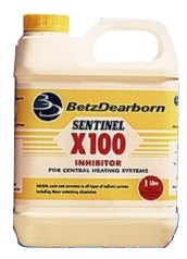
It is important that SENTINEL X100 Inhibitor is used to protect the Heat Bank Thermal Store. 
Use 1 litre per 100 litres of stored water.
Label the unit as protected with the label provided.
Contact Betz Dearborn direct for method statements on 0151 424 5351
Alternatively contact Fernox on 01799 550811
.
6.3 IMPORTANT: The Primary System should be fully flushed and an inhibitor, suitable for the purpose, used to protect both the primary and the Heat Bank Thermal Store systems. Betz Dearborn SENTINEL X300 should be used to flush the Primary System prior to filling new systems. Use SENTINEL X400 for existing systems. Please contact Betz Dearborn direct for method statements on 0151 424 5351, or alternatively contact Fernox on 01799 550811.
6.4 Everest Heat Bank Thermal Stores are fitted with a manual vent to the F&E Tank, fitted with a lockshield valve. This can be opened during initial filling to speed up filling. Once the unit has been filled the lockshield valve should be closed.
6.5 The unit is filled by using the filling loop provided. The unit MUST be watched constantly to prevent overflow. CHECK THE WATER LEVEL IS CORRECT USING THE FILL LEVEL INDICATOR, AND ENSURE THAT THE FILLING LOOP IS DISCONNECTED UFTER USE.
6.5.1 Connect a short length of hose from the Manual Water Level Test/ Drain [56] into a bucket. 
Connect the Filling Loop [54] to the Filling Point [9]
Open the Isolating Valve [10] in the Vent Pipe [8].
Slowly Open the Isolating Valve on the Filling Loop, and the unit will start to fill. 
Fill until water is discharged via the Manual Water Level Test/ Drain [56].
6.5.2 Excess water should be drained off via the Manual Water Level Test / Drain.
Close the Isolating Valve [10] in the Vent Pipe [8].
Disconnect and cap the Filling Loop [54].
6.6 To fill the Primary System, connect the Filling Loop provided to the Primary Filling Point, and open. Disconnect the filling loop after use.
6.7 The Pressure Relief Valve is fitted with a Pressure Gauge to aid filling.
6.8 Check that all air locks in the Primary System are cleared properly, and all Radiators bled.
6.9 IMPORTANT: Check that the Primary System is filled to a suitable pressure as per requirements for sealed systems.