DEDICATED PRESSURE SYSTEMS LTD.

Telephone 01372 803 675
Fax 01372 803 678
Email dps@heatweb.com
 
Internet http://www.heatweb.com

The Institute of Plumbing

R/O Shops, 9-19 Manor Green Road, Epsom, Surrey KT19 8RA
  

Installation Notes  1613-1  

07/07/00

Contents:
1. Introduction
2. General Requirements
3. Mains Water Supply
4. Connections
5. Wiring
6. Filling
7. Commissioning
1 Introduction
1.1 A Heat Bank Thermal Store is an Advanced Integrated Thermal Store providing very high flow rates of Mains Pressure Drinkable Hot Water for domestic properties. The Heat Bank Thermal Store stores Heat Energy which can be utilised to provide domestic hot water. This heat energy is retained within the Heat Bank Thermal Store by the use of 'CFC free' foam insulation.
1.2 A plate heat exchanger separates the pressurised mains water from the stored water, while allowing rapid transfer of heat. While the mains water pressure can be anything from 0.5 to 6 bar, the stored water is not pressurised, allowing the Heat Bank Thermal Store to be vented to atmosphere. The mains hot water is not stored and is therefore drinkable, and removes the need for a cold water storage tank. There is no chance of the introduction of Legionnaires' Bacteria into the domestic supply.
1.3 The stored water does not change. The build up of scale within the cylinder is therefore eliminated and extra system protection can be achieved by the addition of inhibitors. If required, anti-freeze may also be added.
1.4 The stored water can be heated to a maximum of 90°C thereby increasing the amount of heat energy available for use, while the use of CFC Free Foam Insulation (to British Standards 699, 1566 & 4735) keeps the heat within the stored water.
1.5 Provision of Domestic Hot Water (diagrammatic).

Using a plate heat exchanger to transfer heat, a method referred to as forced convection, provides heat transfer rates of up to 100kW (340,000 Btu/h). thereby providing mains pressure hot water at up to 30 litresper minute


1.5.1 When a hot water outlet is opened the resulting flow of water is sensed by the Flow Switch, which in turn switches on the Heat Bank Thermal Store Pump. Switch will turn off the Pump, thereby using energy only when required.
1.5.2 The Pump draws hot stored water from the top of the Heat Bank Thermal Store and passes it through the Heat Exchanger and back into the bottom of the Heat Bank Thermal Store through a diffuser tube. This prevents turbulence within the unit, thereby increasing efficiency.
1.5.3 As the stored water passes through the Heat Exchanger its heat is rapidly transferred to the Mains Water also running through the Heat Exchanger but separated from the stored water by numerous plates.
1.5.4 When the hot water outlet is closed, the Flow Switch will turn off the Pump, thereby using energy only when required.
1.6 The Heat Bank Thermal Store uses an Indirect Primary Heating Coil to transfer heat to the stored water.
2 GENERAL REQUIREMENTS
2.1 Read these instructions in conjunction with those of the primary heating appliance before attempting installation.
2.2 Installation shall be in accordance with the latest editions of :
2.3 BS5449 Forced circulation hot water systems
2.3.1 BS6700 Water services for domestic use
2.3.2 The Model Water Bye-laws, the local Water Undertaking Bye-laws and the I.E.E. Wiring Regulations.
2.4 Installation should only be carried out by suitably qualified installers. There is no requirement for approved training in regard to the installation of pressurised or unvented storage cylinders.
2.5 Do not attempt to lift the unit using the pre-fabricated pipework.
2.6 All pre-made connections should be checked & tightened if required prior to installation.
2.7 Pre-Fitted Pumps may need repositioning by installer and inlet connections made watertight. Ensure that access can be made to the Pump Isolating Valves.
2.8 The domestic hot water operates at mains pressure, therefore all pipework and fittings must be suitable for the maximum pressure and temperature duty. Please check that the maximum supply pressure does not exceed 6 bar, and if necessary a Pressure Reducing Valve should be fitted onto the incoming mains. The Heat Bank Thermal Store remains unpressurized at all times.
2.9 Connections in 22mm to the Heat Bank Thermal Store are provided by metric compression bosses, supplied with nuts and olives for direct connection to pipework. BSP fittings should not be used. Spare Nuts are available upon request.
2.10 The stored water in the Heat Bank Thermal Store must be protected with a suitable chemical scale & corrosion inhibitor. See Section 6.
2.11 The cylinder must be installed to allow access to all fitted components for maintenance purposes. This will include the removal and replacement of the Immersion Heater(s).
2.12 Push Fit Connections
2.13 Certain pipework connections are made using push-fit fittings. A Disconnecting Tool will be required to disconnect push-fit joints. Disconnecting Tools & more information can be obtained via our spares departement.
2.13.1 When connecting to a push-fit fitting:
2.13.2 Any soldered joints in adjoining pipework should be made prior to connection to the push-fit fitting.
2.13.21 Cut tube square using a rotary pipe cutter - do not use a hacksaw to cut the tube.
2.13.22 Check that the end of the tube is free from burrs and sharp edges or damage will occur to the O-Ring in the push-fit fitting.
2.13.23 Allow 27mm of pipe for insertion into the fitting plus 10mm of pipe to allow use of a disconnecting tool.
2.13.24 Insert the tube through the release collar of the fitting to rest against the grab ring.
2.13.25 Push the tube in firmly until it reaches the tube stop with a positive 'click'.
3 COLD MAINS SUPPLY.
3.1 The Cold Mains supply should not exceed 5 bar pressure, or a flow rate of 30 litres per minute.
3.2 IMPORTANT: A Mains Isolating Valve must be fitted onto the incoming mains within the cylinder cupboard within
3.3 IMPORTANT: A Y-Pattern Strainer (supplied loose) must be fitted onto the incoming mains. The Y-Pattern Strainer should be fitted down-flow of the Isolating Valve in a position to enable servicing.
3.4 In areas of hard water it is recommended that a In-Line Scale Inhibitor be fitted on the incoming mains supply, and installed as per manufacturers instructions.
3.5 In areas where hard water is known to be a problem, it is recommended that an Electronic Scale Inhibitor be fitted on the incoming mains supply. Details available upon request
4 CONNECTIONS TO Heat Bank Thermal Store.
4.1 Cold Mains In.
4.2 Hot Water Out.
4.3 Flow from Boiler.
4.4 Return to Boiler
4.5 Flow to Heating Circuit
4.6 Overflow [12]
4.6.1 The Overflow must be taken to a minimum distance of 150mm above the top of the Heat Bank Thermal Store.
4.6.2 The Overflow may discharge a maximum distance above the unit of 1 metre.
4.6.3 Should the overflow discharge (to atmosphere) at a level lower than the top of the Heat Bank Thermal Store, then a Tundish must be fitted, level with the top of the Heat Bank Thermal Store, and with the remainder of the overflow in 22mm Copper.
5 WIRING
5.1 All cable should be Heat Resistant, and suitable for 240V 50Hz supply.
5.2 The controls supply to the wiring centre should be fused rated to 3amps to BS.1362.
5.3 Wire the Immersion Heater to a suitable switched supply, fused rated to 16 amp.
5.4 Check the Immersion Heater Thermostat is set to 80°C.
5.5 Wiring to Vokera Mynute Boiler
5.5.1 A 4 Core cable (Brown,Blue, Black and Green / Yellow) of at least 0.75mm wire, should be used to wire the boiler to the Smartfit Wiring Centre.
5.5.2 The Vokéra Mynute Boiler is wired to the Smartfit  wiring centre as shown


The Heat Exchanger Pump shares the same terminals as the Mains ElectricalSupply.

5.5.3 If you wish to be able to isolate the boiler seperately from the rest of the system, then the 4 Core Cable should be run through a suitable switch. a 3 Pole Switch is preferable, isolating the Brown, Black, and Blue wires, and leaving only an Earth connection to the boiler.
If a switch is not fitted, then the boiler can be isolated seperately by turning off the supply to the Heat Bank Thermal Store wiring, removing the boiler connections from within the Smartfit Wiring Centre on the Heat Bank Thermal Store, and turning back on the supply to the Heat Bank Thermal Store.
5.6 Wire the Smartfit Room Unit to the Smarfit Wiring Centre using a low current 2 core cable, as specified in the Honeywell instructions. NOTE: The connection is 12 V dc, and it does not matter which way round the wires are connected.
6 FILLING.
6.1 IMPORTANT: SYSTEMS SHOULD BE FLUSHED AND PROTECTED IN ACCORDANCE WITH BS7593-1992. Please check Boiler and other Primary Equipment's Installation Instructions prior to filling.
6.2 It is important that SENTINEL X100Inhibitor is used to protect the Heat Bank Thermal Store. 
Use 1 litre per 100 litres of stored water.
Label the unit as protected with the label provided.
Contact Betz Dearborn direct for methodstatements on 0151 424 5351
Alternatively contact Fernox on 01799 550811
.
6.3 IMPORTANT: The Primary System should be fully flushedand an inhibitor, suitable for the purpose, used to protect both the primary andthe Heat Bank Thermal Store systems. Betz Dearborn SENTINEL X300 should be used toflush the Primary System prior to filling new systems. Use SENTINEL X400 forexisting systems. Please contact Betz Dearborn direct for method statements on0151 424 5351, or alternatively contact Fernox on 01799 550811.
6.4 Stowaway Heat Bank Thermal Stores are filled using the Filling Loop provided.
6.4.1 Check that the valve on the filling loop is closed (at right angles to the pipework). Remove the Blanking Cap from the Filling Loop and connect to the Filling Point.
6.4.2 
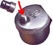
Slowly Open the Isolating Valve on the Filling Loop, and the unit will start to fill. As it fills air will be discharged from the Automatic Air Vent.
IMPORTANT: filling to quickly will cause excess water to be discharged via the overflow.If this happens, do not fill as quickly.
NOTE: To speed up filling, it is possible to unscrew the cap from the top of the Automatic Air Vent, and depress the plastic insert, as shown in the photo. This allows air to vent quicker, and the unit to fill with water quicker.


6.4.3 Continue to fill the unit until no more air is dischared from the automatic Air Vent. Remove the Cap from the Automatic Air Vent, and depress the plastic insert - If the unit is full then water will be discharged.
6.4.4 Disconnect the Filling Loop.
6.4.5 Blank off the Filling Loop with the fitting supplied. Also, unscrew and remove the lever from the Filling Loop to prevent tampering.
6.5 The Primary System is filled using the Filling Loop provided.
6.6 Check that all air locks in the Primary System are cleared properly, and all Radiators bled.
6.7 When using a Vokera Mynute Boiler, the system charge pressure should be 1 bar.
7 COMMISSIONING.
7.1 Set the Room Thermostat to its maximum setting.
7.2 Set the Boiler Thermostat to maximum.
7.3 Ensure that the Cylinder Thermostat is strapped to the unit in good contact with the cylinder wall. 
Check that the Hot Water Temperature on the Smartfit Room Unit is set to 75°C.
7.4 Set the Primary Pump to Speed 3.
7.5 Set the Heat Bank Thermal Store Pump to speed 2.
7.6 Follow any specific commissioning instructions given in the Boiler Installation Instructions.
IMPORTANT: ONLY SUITABLY QUALIFIED INSTALLERS CAN COMMISSION A GAS BOILER.
7.7 Turn on the electrical supply.
7.8 Bleed all pumps as described.
7.9 Run through the operation of the system as follows:
7.9.1 Set the programmer to Hot Water ON.
7.9.2 The boiler should fire, and the primary pump turn on. Within a short time (3 minutes) the flow from the boiler should feel hot to the touch. Check that thepipework to the primary coil is also hot. The flow to the central heating shouls not be hot at this stage.
7.9.3 Set the Programmer to Heating ON. The flow to the heating circuit should now get hot.
7.9.4 Turn off both the Hot Water and Heating on the Programmer. The Boiler should stop firing, and the primary pump stop - on sytems where the boiler uses a pump over-run, the pump may not turn off for a few minues.
7.9.5 Bleed the entire system to remove air.
7.9.6 Turn the Hot Water ON to allow the cylinder to fully recover. As it does, adjust the Balancing Valve on the Flow (or return) to the Primary Coil to obtain a temperature difference of approximately 10°C (or as specified in the Boiler Installation Instructions) between the Boiler Flow & Return.
7.9.7 Once the cylinder has recovered, check that hot water is available at all outlets.
7.9.8 Thermostatic Control of Hot Water Temperature

The unit is fitted with a Mixcall III Thermostatic Blending Valve, to control the hot water temperature, and prevent scalding.  

Control Knob Position Min 1 2 3 4 5 6 7 Max
Outlet Temp. (°C) 27 32 38 44 49 53 58 63 67

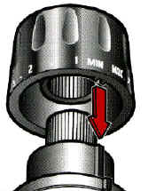
The Valve is adjustable from 27°C to 67°C, and has a lockable head, as shown. Typically the valve should be set to obtain a supply temperature of 65°C, to protect against Legionella.  Check the setting of the Thermostatic Blending Valve by opening a hot water outlet to a low flow rate (approximately 10 litres per minute) and measuring the output temperature. The head of the Blending Valve may be locked in position if required.

The graph shows the pressure drop across the valve for various hot water flow rates.

7.10 Set the Room Thermostat as required.
7.11 Should the incoming mains flow rate exceed the maximum transfer rate for the domestic heat exchanger, the hot outlet temperature will drop. This can be corrected by adjustment of the stop cock on the incoming mains to achieve a flow rate off approximately 26 litres/minute.
7.12 Check that a copy of both the Installation / Users Instructions is left with the Heat Bank Thermal Store, or occupier, as required.