 LIMESCALE
The build-up of limescale in domestic hot water supplies and primary systems is a major problem that all heating engineers should be aware of. Problems are caused when the scale builds on surfaces such as the inside of a copper tube or a pump, to a point where flow rates drop, valves and pumps jam, or system efficiency decreases.
The following information on available scale inhibiting devices has been compiled after talking to a number of various manufacturers. The science behind the devices is still under research and because of the complexity of the physics and chemistry involved it is very difficult to ascertain the true effectiveness of such devices without carrying out extensive laboratory testing. Installation conditions and water quality vary so much that it becomes very difficult to draw conclusions from on-site experience. As of yet, no official standards or methods of testing have been established, so customers often have to take the word of suppliers.
 |
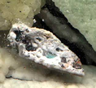
The build up of scale may also cause corrosion. It is often believed that a lining of scale on the inside of a pipe will protect the pipe. This is not true. The picture to the left demonstrates how the build-up of limescale on a metal surface, in this case copper, causes corrosion. The blue colour of the scale is a sure sign of copper corrosion. Scale is a metal salt and is a good conductor of electricity. When it builds up on a metal surface, such as inside the cast iron casing of a pump, it will act as an anode, with the metal becoming a cathode. This anode-cathode setup allows electrons to flow freely between the scale and the metal, allowing corrosion to take place. Also, as the scale is not uniform, the corrosion becomes localised rather than spread evenly over the surface of the metal. In such circumstances, testing the material on the inside of the pump will show the presence both of scale and rust.
|
| The quantity of scale that water can
dissolve depends upon temperature, pressure, and the pH level. As the
temperature of water increases, the volume of scale it holds in solution drops,
resulting in the precipitation of scale molecules into the water. These
molecules join into crystals either on rough surfaces or on other crystals.
Likewise, as the pH increases or as pressure decreases (as it does when water
is flowing along a pipe or through a control), the volume of scale held in
solution drops resulting in scale formation.
It is also worth noting that scale may form in areas where water is turbulent. This is because turbulence causes a drop in pressure which in turn leads to scale forming. |
 |
To prevent scale from being deposited on
surfaces, the aim is to create small 'seed' crystals of scale within the water
upon which any remaining scale will grow, forming larger particles of scale
suspended in the water. These suspended particles pass along pipework, through
any controls, and out through the hot water outlets, without causing problems.
Typically, scale particles in suspension
will typically grow to 50 microns in size. Particles of a size 25 microns may
be visible to the naked eye.
The way to create crystals in the water is
to apply an electric field. Individual molecules of scale align themselves with
the electric field, and move towards each other (by a similar mechanism to the
way electrons moving along a wire). Once in contact the scale bonds together
forming crystals, with the scale atoms in the crystal aligned to the electric
field. Crystals will continue to grow in this fashion.
In-Line Magnetic devices rely on a flow of
water through a magnetic field to generate the required electrical field. The
electric field strength will vary with the flow rate of the water, and will
disappear when the water stops flowing. The electric field is only present
within the vicinity of the magnets, and once scale crystals have moved past the
magnets they will break down and may build up on surfaces.
Non-Intrusive Electronic devices produce
an electric field (sometimes referred to as a radio signal) along the pipe and
within the water. These devices are connected to an electrical supply, and do
not require a flow of water to set up the electric field. Instead, applying an
electrical a.c. signal to signal wires or a non-ferrous core creates the
electric field.
 The critical factor that determines the
effectiveness of the device is the type of signal applied. Research has shown
that a randomly varying 'sinusoidal' signal gives the best results, although
the mechanism is not completely understood. A set square-wave signal has little
effect.
The critical factor that determines the
effectiveness of the device is the type of signal applied. Research has shown
that a randomly varying 'sinusoidal' signal gives the best results, although
the mechanism is not completely understood. A set square-wave signal has little
effect.
The electrical field that is created will
travel along pipework and through water, however the distance will be
determined by the position where pipework is earthed. The position where
pipework is earthed is important because electricity runs toward earth, and if
such a device is to be fitted to protect specific system components then
preferably there should be no earth between the device and the components to be
protected. One should also avoid fitting these devices on a conducting loop,
such as on a loop of copper pipework, as the loop may 'short-circuit' the
electric field, reducing its effectiveness.
It is important when buying these devices
that the electronics are protected against spikes and other variations in the
electrical supply. If not properly protected, then the electronics may soon
fail. It is also worth checking that the device does not need to be reset if
the electrical supply is cut off temporarily.
In-Line Electrolytic devices are basically
self-contained batteries, producing an electric field and current through the
water. The electric field creates grains of scale within the water. Again, the
electric field is only present within the device, and once scale crystals have
moved on they will break down and may build up on surfaces. Like a battery, the
device will have a set life span; the longer the life... the lower the effect
on scale.
Hydroflow Web Site
Scale
within Primary Systems / Thermal Stores
As primary systems and thermal stores are
filled once only, they will initially contain a set quantity of scale, which is
introduced with the filling water. The larger the volume of the primary system
or store, the more initial scale. Typically this volume of scale should not be
a problem, however if the water the system is filled with contains relatively
high levels of scale, then some form of chemical inhibitor should be added,
especially on larger primary systems and thermal stores.
If the system is vented, then some water
may be lost from the feed & expansion (F&E) tank over time through
evaporation. Water may also be lost when radiators are bled or if there is a
leak in the pipework. Whenever water is lost it will be replaced, usually via a
ball valve, and more scale will be introduced. If the level of water loss is
high then the volume of scale in the system will build up until problems occur
- usually in the form of sticking pumps and controls.
If the feed & expansion tank feeding
the system contains relatively warm water, as it often does, then evaporation
will increase. If the F&E tank is not properly fitted with a lid then a
significant amount of water may be lost through evaporation, requiring the
introduction of fresh water, along with more scale, resulting in elevated scale
within the system.
The surface area of water in the F&E
tank, from which evaporation takes place, should also be kept to a minimum -
tall & thin F&E tanks are better than deep & wide tanks. In some
instances, a blanket of Expanded Cross-Linked Polyethylene can be floated on
the surface of the water, cutting down the water-air surface area and hence the
level of evaporation. Alternatively, oil of a specific kind can be added into
the F&E Tank; this will float on the surface of the water acting as a
barrier against evaporation - the oil itself will not evaporate, but will need
to be replaced if the system is drained.
One of the best methods of protecting the
system against scale is to use a Non-Intrusive Electronic device, which will
provide continuous protection.
Example from site in London: A thermal
store unit fitted with an integral F&E tank, 630mm deep & 440mm wide,
installed with the lids not fitted correctly. The water supply used for filling
contained approximately 15° to 20° of Calcium Carbonate (CaCO3), however the
scale content of the water in the store was measured at over 50° CaCO3. By
comparison, a typical water supply in the South contains 15° CaCO3 while one of
the highest levels of scale in England can be seen in Hartlepool where the
content is equal to 45°. A level over 20° is considered very hard.
