![]()
|
Underfloor heating is easily the biggest growing sector of the domestic heating industry. Almost 50% of all our private enquiries are concerned with the installation of underfloor heating, so why all the fuss?
Advantages
Disadvantages
If conducted at the new-build or refurbishment stages, installation is relatively straight forward, with many time saving pipework systems now available on the market to cover all floor types from concrete screeds to suspended timber floors. Converting your house while living in it is possible, although very disruptive. To simplify the installation of a modern system, we have developed a range of units to cover all the system variants we have yet encountered. Contents: TYPICAL COMPONENTS TYPICAL COMPONENTS:
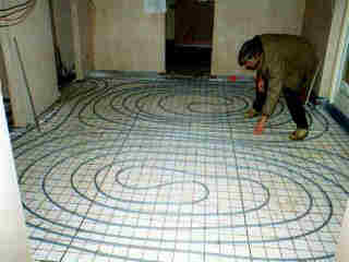
PIPEWORK: PEX All underfloor pipework is plastic, specifically cross-linked polyethylene. They must have an oxygen diffusion barrier to prevent the ingress of oxygen through pipework into the system water. Pipe is supplied in coiled lengths of 100m or more.
Multilayer pipes are a triple layered pipe of cross-linked polyethylene (PE-Xc) sandwiching a layer of aluminium. The tube can be easily bent to shape, and will then retain that shape, making laying and fixing of pipe easier. The specifications for such pipe are exceptional, including 100% Oxygen impermeable, expansion comparable to copper, 10 bar maximum working pressure at 95�C, and 50 years working life guaranteed. The two main manufacturers of such pipe are MULTIPIPE and UNIPIPE. CONTROLS: Dealing with the control setup for an underfloor system can prove to be quite confusing with the range of systems and choices on offer. Most control features are aimed at improving performance and efficiency of a system, and taking automation to various levels. As with all controls, the more advanced controls can be more complicated to set up correctly, and to fault find. They can also be very expensive. The following features should be considered.
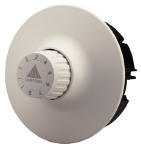
These are the most basic heating control, and is simply a wall mounted temperature thermostat that can be manually adjusted by the user to achieve comfort levels.
These are a more advanced version of the basic room
thermostat, combining with it the functions of a central heating timer.
Thermostats typically have 6 times when the set temperature can be
programmed to. For example, 28�C from 6:00am to 8:00am, dropping to 5�C
(frost protection) until the evening. Although the thermostats have
manual override, allowing the user to easily adjust the room temperature
setting, the stat will automatically reset the set temperature with the
next program setting. This overcomes the problem of users inadvertently
leaving room stats turned up high at night. Night Setback. This is a basic feature built into some room thermostats that will turn down the room set temperatures automatically at night, by typically 6�C. This is a simple feature, and allows heating to be left on at night, without running the expensive of heating the room to full temperatures. Fully programmable room thermostats inherently allow lower night time temperatures to be set up within the program.
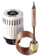
Compensation requires the use of a motorised thermostatic
blending valve to enable the temperature of the underfloor flow to be
altered according to the outside temperatures. This leads to the floor
giving a more consistent heat output rather than the on/off cycle, which
would otherwise result (from the room stat). It also has the effect of
reducing the average temperature of the water coming back to the boiler so
increasing boiler efficiency - especially condensing boilers.
Optimum Start. Instead of setting a time for the heating to come on and hoping that the house will be warm enough, the user enters the time by which the house needs to reach a set temperature. The controller brings the heating on earlier or later as required depending on how cold it has been overnight. Optimisation therefore provides improved comfort rather than efficiency and is particularly suited to houses with a lot of 'thermal mass' and unresponsive heating such as a screed based underfloor system. This is a very advanced feature. CONTROLLING TEMPERATURE OF UFH CIRCUITS:
This operates on the principal that the return temperature is a good indication of floor temperature, so that by maintaining a steady return temperature we can maintain a steady floor temperature and load. This system has been used extensively in Europe for many years, and is a proven method of control, however it is only suitable under the following conditions to ensure no hot-spots occur:
Because of the limit on floor area per valve, it becomes economical to use this system for large underfloor heating areas. However, the valve is perfect for taking small underfloor zones of standard radiator pipework.
The simplest method of controlling the UFH temperature is by using a Thermostatic Mixing (blending) Valve. This is a three port valve that works automatically to mix the hot supply and UFH return to achieve a set output temperature, basically adding hot water into the UFH circuit to maintain temperature. The temperature is typically set by turning the head of the valve, which can often be locked into a certain position.
A three port setup does allow the UFH pump to draw from the boiler circuit, or thermal store, without the need for another pump. The disadvantage of this type of valve is that it is manually set, and does not allow the temperature to be adjusted by the control system. This rules out weather compensation as an option, unless the end user can get used to manually setting the valve according to the season or outdoor temperature.
For very large pipework systems, requiring over 3m3/hour of flow rate, their are larger valves available. These will usually consist of a three port brass valve, and a sensor/actuator with a bulb type sensor that is mounted in the pipework and connecting to the actuator with a capillary tube (typically 3m long). The Danfoss Randall VMV Valves and RAVK Sensor are common.
Motorised Three and Four Port Valves. Such valves are electronically controlled to mix the hot supply and UFH return to achieve a set output temperature, adding hot water into the UFH circuit to maintain temperature. The valves is powered by a motor, which is in turn driven by the control system. Temperature readings are measured from sensors in the pipework. This is a far more complicated system that a simple thermostatic valve, however it enables weather compensation to be achieved automatically by the control system. These valves will also require sizing in accordance with the pump due to the pressure losses across them, as well as the maximum differential pressure they can take.
The four port model, shown above, ensures that both the mixed and supply circuits see no resistance to flow - instead of one port closing down, the flow is diverted out the fourth port. This is more suited to larger commercial systems - the matter of differential pressure becomes less important as the valve never has to shut down a circuit.
Injection Systems. The UFH pump is now sized to match the UFH circuit alone. The boiler pump is sized to maintain boiler flow rates, not having to overcome any UFH. The injection pump has very little resistance to overcome.
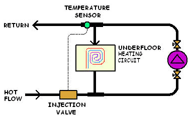
An injection valve can be used to control the injection rate, controlled in turn by the control system in conjunction with the UFH flow sensor. Thermostatic control can be achieved by the use of a two port valve with a remote temperature sensor. This overcomes the need, and advantages, of having the control system. Other Injections systems (2nd schematic) work by the creation of an additional circuit between the hot water supply (boiler) circuit and the UFH circuit. A pump fitted into this additional circuit is used to inject hot water into the UFH circuit. The temperature of the UFH circuit is thus controlled by the rate that hot water is injected.
It is also possible to for the control system to modulate the pump speed, overcoming the need for an injection valve. Sometimes there will be an additional sensor on the hot flow from the boiler. Injection systems have the advantage of achieving fully automatic temperature control, with no motorised valves. Pumps on their own provide better circulation, are more reliable, and much easier for a service engineer.
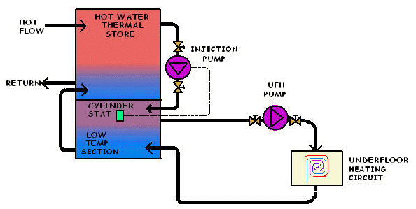
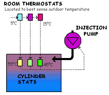
Twin Zone Thermal Store Injection System. With a thermal store it is possible to simplify controls further by dedicating a section of the store to run at a lower temperature. A cylinder thermostat controls the injection pump to keep the lower section up to the required UFH flow temperatures.
The use of more than one cylinder thermostat in the lower section can allow different UFH flow temperatures to be selected. When used in conjunction with simple room thermostats to sense outdoor temperature (located in, for example, the garage), this can provide a simple form of effective weather compensation using cheap, readily available components. Overheat protection can be provided by another stat. |
|||||||||||||||||||||||||||||||||||||||||||||||||||||||||||||||||||||||||||||||||||||||||||||||||||||||||||||||||||||||||||||||||||||||||||||||||||||||||||||||||||||||||||
|
BASIC DESIGN: Calculating the central heating and hot water loading. The first step in designing any heating system is to calculate the required central heating output to match the heat losses (and gains) for each room. The Barlo Heatload Calculator is a simple piece of software that can be downloaded free and makes it easy to perform all the required calculations.
Are radiators required as well ? Reasons why a radiator may be used include:
It is worth remembering that the higher the thermal mass of the underfloor system, the longer the heat up times. Quite quick heat up times can be achieved with a thinner screed above floor insulation. Fan convectors are another consideration as they have higher heat outputs, and can be used sparingly to accelerate initial heat up.
Deciding if primary distribution pipework (up to manifolds) is to be blended. Water can be pumped from the boiler / thermal store to underfloor manifolds...
Centralising the temperature control makes for a simpler system, and allows weather optimisation to be more easily implemented. However, running pipework at full temperatures allows for radiators to be better used. Radiators tend to require water at higher temperatures,
83�C, as opposed to 40-55�C for underfloor heating. Sending very hot
water round an underfloor circuit may cause the screed to crack, or floor
temperatures to get uncomfortably high. Temperature controls of some
sort are therefore required to limit the temperature of the water going to
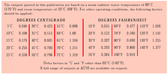
underfloor circuits. Table of Radiator Outputs vs. temperature.
Taken from Barlo Radiators website.
Calculating lengths and densities of pipework required. Once the heat losses of the property are known, the required power output [W/m2] of the floors is calculated by dividing floor area for underfloor heating pipes [m2] by heat losses/output [W]. Calculations should be done for each room individually. The heat losses should take account of any radiator input, which should be deducted from the required UFH output. Also, the floor area in rooms may be reduced because of fixings, such as in kitchen cupboards, or bathtubs. Allow for this when working out the floor area to use in calculations. The following table, from Hilton-Croft UFH, is for a typical PEX pipe system.
*
maximum acceptable heating circuit lengths including pipe 'tails' to the
manifold. Take a 180m2 property with 13.5 kW heating load, requiring 75 W/m2. With 50�C flow, floor temperature 25.7�C, 10 x 60m pipe runs will provide (this should really be done room by room). The total flow rate would be 1.16 m3/hour (20 ltrs/min) at a pressure loss of 50mbar (0.5m head).
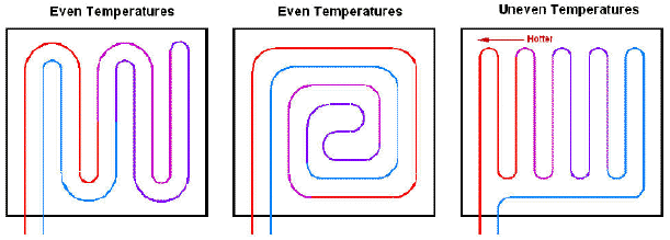
Basic Heating Pipework Layout Once heat losses and lengths of required UFH pipework have been calculated. The following points should be kept in mind when working out pipework layouts:
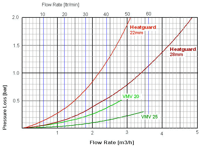
Sizing of thermostatic mixing valve and UFH pump Looking at the pressure loss graphs for typical UFH Blending Valves (graphs taken from RWC web site), in 22mm and 28mm, we can see (continuing the example) that at 20 ltrs/min the system looses 0.4 bar (4m head) through a 22mm valve, or only 0.15 bar (1.5m head) through the 28mm valve.
Although a bigger pump would work, to avoid system noise it is better to use the 28mm blender, which together with the pipework only looses 2m head. We still then have 2.4m spare head of pump pressure to overcome other manifolds, actuators and balancing valves. Such pump curves can be generated using Grundfos WebCAPS. These calculations are based on centrally provided mixing for the whole property. If there is more than one manifold fitted with its own mixing valve and pump, then the calculations need to be performed separately for each sub system. It is also often advisable to incorporate an over-temperature valve, to isolate the flow to the underfloor in case of a failure of the blending valve to function. Over a period, high temperature water >60�C may cause screeds to crack, so protecting against this is wise. The simplest form of protection is to use a stat that will isolate the power to the UFH pump and actuators. Full protection will involve a dedicated isolating valve of some sort - there are both electrical (stat + actuated valve) and purely mechanical (valve with bulb sensor) methods. If this valve is fitted in the UFH circuit then it will need to be accommodated in pressure loss calculations.
Sizing Boiler. Once a figure for the total heat losses of the property are calculated, the hot water requirements can be roughly calculated as allowing 2.5kW per person. This is based upon a bath of hot water for each person, recovered in two hours. The total of hot water and heating loads gives a minimum boiler size. It is wise to oversize a boiler slightly, maybe up to 30%, but higher output boilers may suffer from cycling problems, reducing efficiencies, especially on fixed-output boilers. If a thermal store is to be tied into the system then cycling can be overcome, even for large fixed output boilers.
Sizing Boiler Pump. The boiler will require a pump suitably sized for its output, although sometimes boilers come pre-fitted with a suitable pump. A required flow rate at full burn, can be determined from the output of the boiler as follows (typically the boiler temperature drop is around 10�C):
Systems should always have a by-pass of some sort. Unless an automatic by-pass is used, the re-circulation through the by-pass (typically low or no load) will need to be added to the flow rate. It is advisable to use an automatic by-pass as it overcomes the need to worry about the adverse affects of fixed by-passes on flow rates and pressures. Other valves that may need to be incorporated into the design include:
Allowances must also be made for pipework from the boiler to manifolds and/or hot water store.
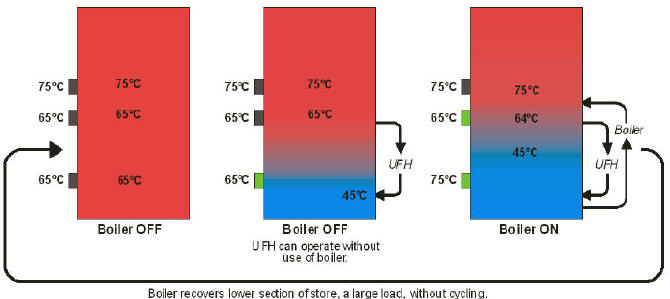
Buffer Store Operation. The only way to ensure that condensing boilers run continuously in condensing mode for heating, or to overcome nuisance cycling of boilers, is to tie a thermal store into the underfloor system. The store acts as a buffer between the heating load and the boiler output. It saves up heat energy while the boiler is firing, and then uses that stored heat to keep the heating going once the boiler stops firing. This way the boiler does not have to fire so often, and will burn for longer when it does.
With underfloor heating one only needs a flow temperature of 55�C max. The lowest temperature in the system is the underfloor return, at between 30 and 45�C, so ideally we want to only ever heat water from 45�C through to 65�C to maintain underfloor heating (assuming 20�C rise is suitable for boiler). This is easily achieved with a buffer store by setting up cylinder thermostats accordingly. The boiler will not fire until both the lower thermostats are calling for heat, and will then continue to fire until both are satisfied. The thermostats should be tweaked down so that the boiler re-heats water in one pass - a second pass would involve return water over 60�C.
With non-condensing boilers, where buffer use is to overcome cycling, only the lower two cylinder thermostats are needed, both set to 75�C. Buffer stores are also useful when trying to incorporate solar panels into a system. A coil in the base of the store allows heat to be transferred to the coldest point of the store, and then to be used for underfloor heating.
Sizing Hot Water Store. When calculating size of hot water store, you can use our Waterload Calculator. As a rule of thumb, we allow 90 litres storage per bath, and 60 litres per shower, within the period of maximum demand. If a thermal store is to be used, then additional storage may be added to allow for buffer operation. Extra storage may also be required if solar panels are to be utilised. Special care has to be taken on electrically heated systems as the smaller the store, the less able it is to store up heat provided on cheap rate electricity. Special care should also be taken where there are body jets, large shower roses, or a general desire to spend a considerable time in the shower. DPS Thermal stores are available in base unit diameters of 40cm, 45cm, 50cm and 60cm, with heights from 85cm up to 2m, making a range of capacities from 90 litres to 500 litres.
Sealed or Vented Primary System. Generally it is best to opt for a sealed primary system - in other words, one which is pressurised rather than tank fed. Sealed systems have the following main advantages:
If you have a sealed system boiler, or certain other makes of boiler, then a vented system is not an option. However, vented systems do have some advantages, providing that you can live with a 12 gallon (12x12x20") feed & expansion tank in the loft.
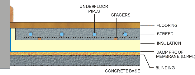
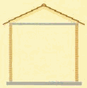
FLOOR DESIGN: Screeded Floors
A blinding layer of sand is added to fill voids and to provide a smooth firm surface free from sharp particles, this it is essential to avoid puncturing the DPM. DPM stands for Damp Proof Membrane. It is required when laying wood flooring or laminate flooring onto cementous substrates e.g. concrete, ceramic, marble, tarmac/bitumous surfaces. The DPM will prevent sweating and any moisture ingress from the sub-floor. Floor insulation is typically rigid foam thermal insulation board with reflective foil facings (Celotex). Available in varied thicknesses and board sizes (50mm x 1200x2400mm, 1200x1000mm...)
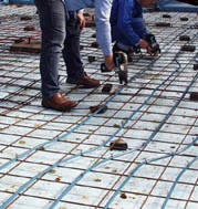
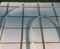
The pipes are fixed to a steel mesh, using simple wire clips. The
mesh is lifted clear of the insulation with spacers prior to filling with
screed.
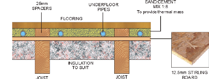
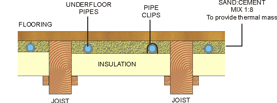
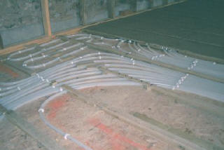
Suspended Floors
The suspended floor methods shown below use a Sand 1:8 Cement mix to act
as a thermal mass, and spread the heat load. This is a cheaper
alternative to using aluminium spreader plates. ABOVE JOIST:
Some links to underfloor companies:
|
|||||||||||||||||||||||||||||||||||||||||||||||||||||||||||||||||||||||||||||||||||||||||||||||||||||||||||||||||||||||||||||||||||||||||||||||||||||||||||||||||||||||||||

.jpg)
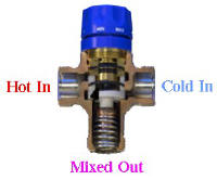 Thermostatic
Mixing Valve.
Thermostatic
Mixing Valve.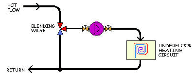 These
valves have been used for many years, mainly to control hot water to taps
and showers, and are very reliable and cost effective. They do need
to be sized correctly in conjunction with the pump (see later section) to
obtain the correct system flow rates, as they restrict the flow.
These
valves have been used for many years, mainly to control hot water to taps
and showers, and are very reliable and cost effective. They do need
to be sized correctly in conjunction with the pump (see later section) to
obtain the correct system flow rates, as they restrict the flow.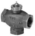
 Thermostatic Valves for Very High Output.
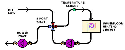

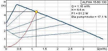 The
pump curve for a standard Grundfos Alpha 15-60 pump show that at 1.16 m3/hour the pump
can generate 4.4m head of pressure. The calculations show a total
pressure loss through the pipework and 22mm mixer of 4.5m, however this is
greater than the pump can provide.
The
pump curve for a standard Grundfos Alpha 15-60 pump show that at 1.16 m3/hour the pump
can generate 4.4m head of pressure. The calculations show a total
pressure loss through the pipework and 22mm mixer of 4.5m, however this is
greater than the pump can provide.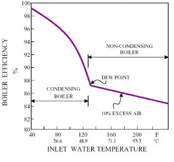 Reducing cycling in itself will improve efficiency,
however gains are also to be achieved by keeping return temperatures to
the boiler low at all times. Without a thermal store this is very
difficult to achieve, unless the boiler has built in electronics. This is
because to maintain minimum flow rates through the boiler at low heating
loads, water will flow via the by-pass to the return, raising the
temperature. This cycle will continue until the water in this loop
reaches 80�C (upper boiler stat), by which time the return temperature is
above 60�C. Boiler efficiencies are better the lower the return
temperature and at 60�C condensing efficiencies are not good.
Reducing cycling in itself will improve efficiency,
however gains are also to be achieved by keeping return temperatures to
the boiler low at all times. Without a thermal store this is very
difficult to achieve, unless the boiler has built in electronics. This is
because to maintain minimum flow rates through the boiler at low heating
loads, water will flow via the by-pass to the return, raising the
temperature. This cycle will continue until the water in this loop
reaches 80�C (upper boiler stat), by which time the return temperature is
above 60�C. Boiler efficiencies are better the lower the return
temperature and at 60�C condensing efficiencies are not good.